2.2.2Tutorial
For this tutorial, let’s consider a hypothetical PLC that we’ll set up for simulation in SimServe. Let’s assume we have a PLC that controls two pumps with the register list shown below:
| Address | Function |
|---|---|
| Coils | |
| 0x00001 | Pump 1 run command |
| 0x00002 | Pump 1 alarm reset |
| 0x00011 | Pump 2 run command |
| 0x00012 | Pump 2 alarm reset |
| Discrete Inputs | |
| 1x00001 | Pump 1 480VAC power fail |
| 1x00002 | Pump 1 24VDC power fail |
| 1x00003 | Pump 1 fail to start |
| 1x00004 | Pump 1 fail to stop |
| 1x00005 | Pump 1 overspeed |
| 1x00006 | Pump 1 discharge pressure high |
| 1x00007 | Pump 1 suction pressure low |
| 1x00008 | Pump 1 torque high |
| 1x00009 | Pump 1 motor housing temperature high |
| 1x00010 | Pump 1 pressure seal leak |
| 1x00011 | Pump 1 oil pressure low |
| 1x00012 | Pump 1 ambient temperature low |
| 1x00013 | Pump 1 water temperature high |
| 1x00014 | Pump 1 lockout active |
| 1x00015 | Pump 1 e-stop active |
| 1x00016 | Pump 1 in local |
| 1x00021 | Pump 2 480VAC power fail |
| 1x00022 | Pump 2 24VDC power fail |
| 1x00023 | Pump 2 fail to start |
| 1x00024 | Pump 2 fail to stop |
| 1x00025 | Pump 2 overspeed |
| 1x00026 | Pump 2 discharge pressure high |
| 1x00027 | Pump 2 suction pressure low |
| 1x00028 | Pump 2 torque high |
| 1x00029 | Pump 2 motor housing temperature high |
| 1x00030 | Pump 2 pressure seal leak |
| 1x00031 | Pump 2 oil pressure low |
| 1x00032 | Pump 2 ambient temperature low |
| 1x00033 | Pump 2 water temperature high |
| 1x00034 | Pump 2 lockout active |
| 1x00035 | Pump 2 e-stop active |
| 1x00036 | Pump 2 in local |
| Analog Inputs | |
| 3x00001 | Pump 1 run speed |
| 3x00002 | Pump 1 suction pressure low |
| 3x00003 | Pump 1 discharge pressure |
| 3x00004 | Pump 1 VAC voltage |
| 3x00005 | Pump 1 VDC voltage |
| 3x00006 | Pump 1 flow rate |
| 3x00011 | Pump 2 run speed |
| 3x00012 | Pump 2 suction pressure |
| 3x00013 | Pump 2 discharge pressure |
| 3x00014 | Pump 2 VAC voltage |
| 3x00015 | Pump 2 VDC voltage |
| 3x00016 | Pump 2 flow rate |
| Holding Registers | |
| 4x00001 | Pump 1 run speed setpoint |
| 4x00002 | Pump 1 run time total hours |
| 4x00003 | Pump 1 flow total |
| 4x00011 | Pump 2 run speed setpoint |
| 4x00012 | Pump 2 run time total hours |
| 4x00013 | Pump 2 flow total |
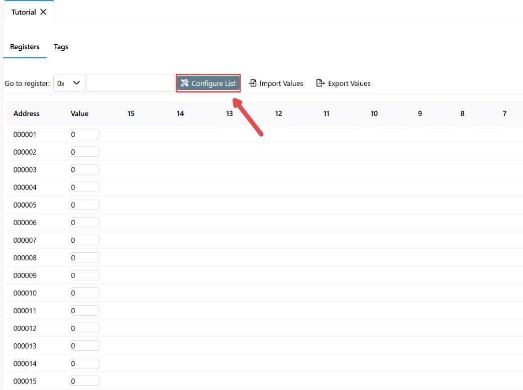
Start by clicking the “Configure” Button to open the “configure register list” popup.
Step 1: Configuring prefixes
First configure the device’s primary table prefixes to match the real device’s register list. Referencing the device’s register list, we can see that the device has the following prefixes:
| Table | Prefix |
|---|---|
| Coils | 0x |
| Discrete Inputs | 1x |
| Analog Inputs | 3x |
| Holding Registers | 4x |
Given that SimServe’s default prefixes match the device’s prefixes, they can be left as is.

Step 2: Configuring Modbus blocks
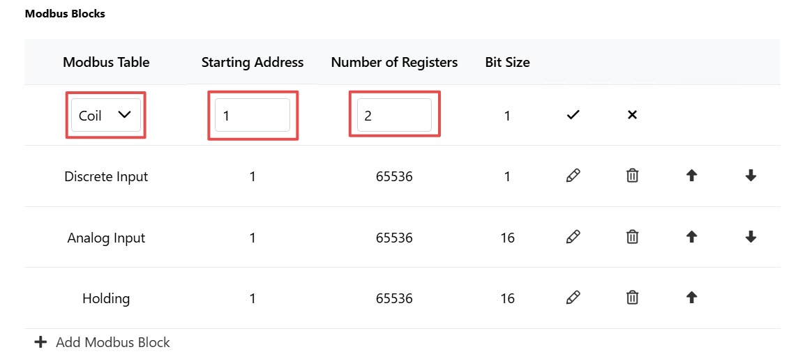
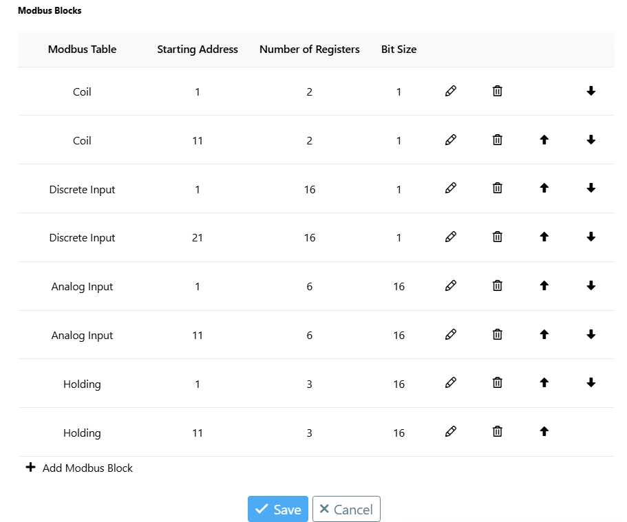
- Modify the first coil block, which exists by default, to contain the coil registers for pump 1. When referring to the device register list, we see the first coil starts at address 1 and there are two consecutive coils, so place value 1 for starting address and 2 for number of registers.
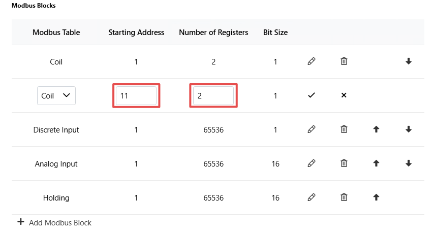
- Noticing a gap between registers for pump 1 and pump 2, create a second set of coil registers. For the second coil block, we must set the starting address at register 11 and number of registers at 2.
- Continue the above steps for the rest of the tables following the reference sheet. After completing, the Modbus blocks should look like this:
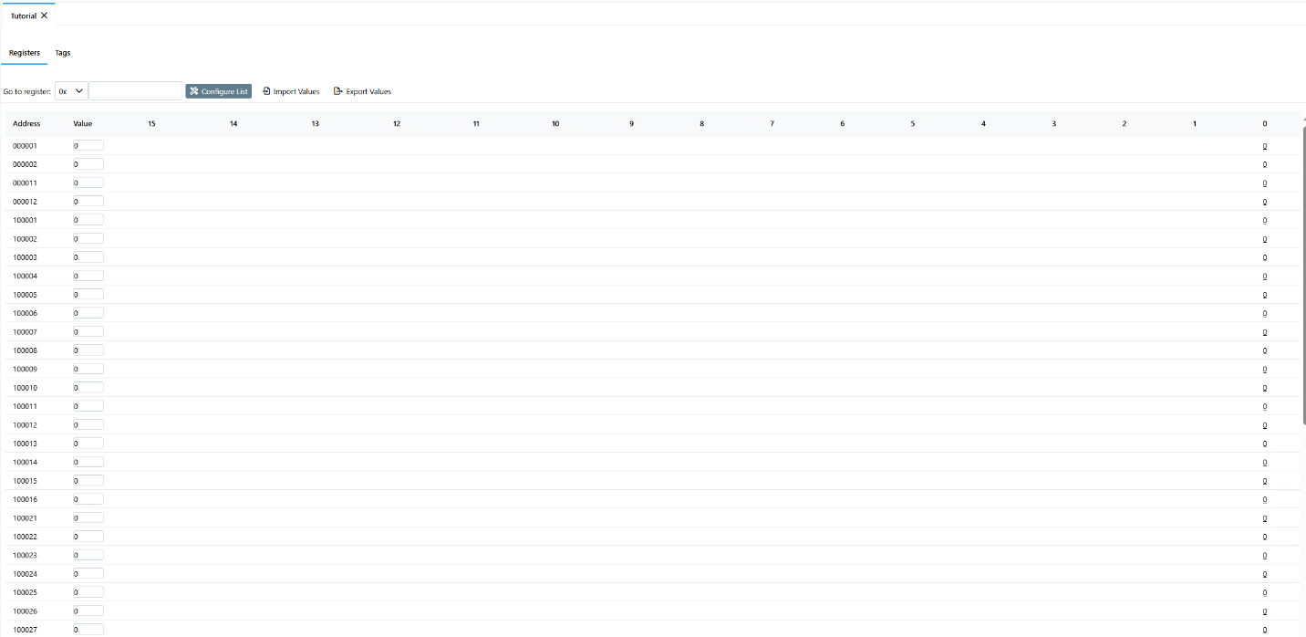
- Now, when viewing the register list, we can see that the list accurately reflects the registers of the PLC we are simulating.