
2.1.2.4New Network of Modbus Devices
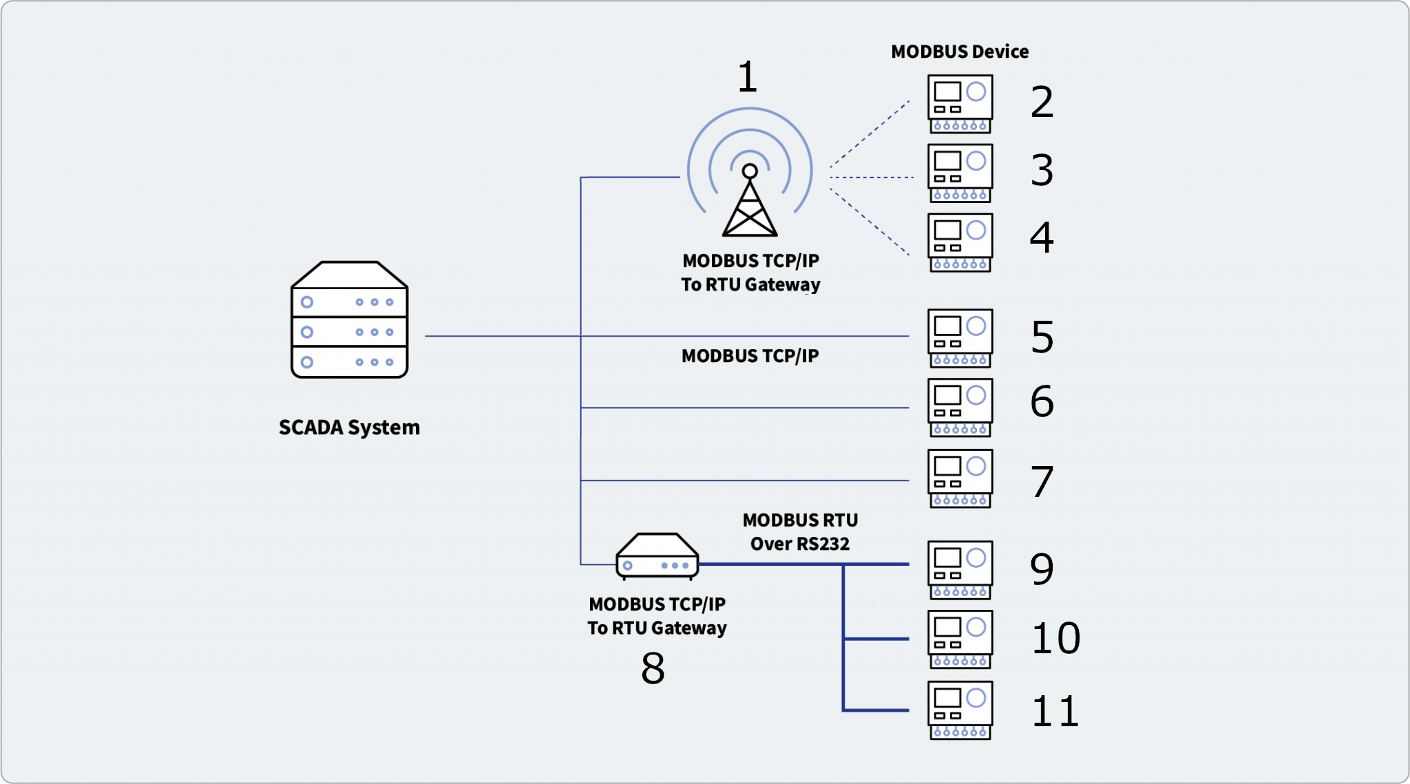
This will explain how to setup SimServe to act as a sophisticated network of Modbus slave devices. A schematic of the network is shown below:
To setup the simulation, follow the steps below.
-
Start with simulating network item 1 from the figure above. Network item 1 will be treated as a gateway — a device that converts from one communication protocol to another. In this case, we'll setup a gateway that converts Modbus TCP to Modbus RTU.
-
Click on New Network Item in the network tree.
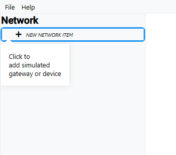
New Network Item -
Fill out the New Network Item form as described below and click Save.
- Name — Enter any preferred name. For this example, we'll use
NetworkItem01. - Network Item Type — Select Gateway.
- Protocol — Select MBTCP-MBRTU.
- IP Address — Enter the IP address of the real gateway. In this example, we'll use
172.31.41.70. Please note, the computer must also have IP address172.31.41.70. Consult Windows documentation to add this IP address. - Port — Enter the TCP/IP port used for Modbus communication on the real gateway. In this example, we'll use
502. Most devices use port 502 by default.
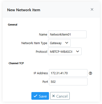
Network Item 01 Filled Out - Name — Enter any preferred name. For this example, we'll use
-
-
Now we'll simulate network item 2. This network item is a device that uses the Modbus RTU protocol. We'll create the device underneath the
NetworkItem01gateway so that the Modbus master can communicate to it through the gateway using Modbus TCP.-
Expand
NetworkItem01in the network tree, and then click on New Network Item underneathNetworkItem01.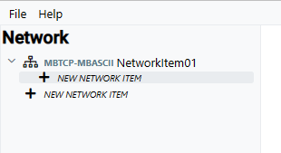
New Network Item Under Device -
Fill out the New Network Item form as described below and click Save.
- Name — Enter any preferred name. For this example, we'll use
NetworkItem02. - Slave Address — Enter the slave address that's used by the real device. For this example, we'll use
1. - Remaining Fields — Leave as default.
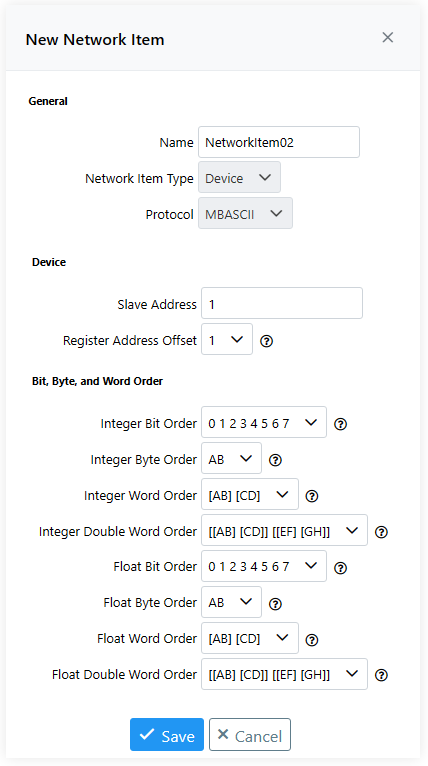
Network Item 02 Filled Out - Name — Enter any preferred name. For this example, we'll use
-
-
Repeat step 2 for network items 3 and 4. For network item 3, set the slave address to
2. For network item 4, set the slave address to3. Upon completing this step, the network tree should appear as shown below: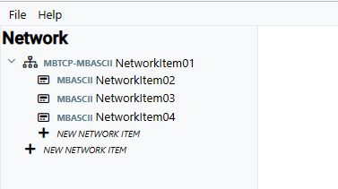
Network Items 3 and 4 -
Now we'll simulate network item 5. This network item is a device that uses the Modbus TCP protocol. We'll create the device in the root of the network tree so that the Modbus master can communicate directly to it, not through a gateway.
-
Click on New Network Item in the root of the network tree.
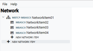
New Network Item Root -
Fill out the New Network Item form as described below and click Save.
- Name — Enter any preferred name. For this example, we'll use
NetworkItem05. - Network Item Type — Select Device.
- Protocol — Select MBTCP.
- IP Address — Enter the IP address of the real device. In this example, we'll use
172.31.41.71. Please note, the computer must also have IP address172.31.41.71. Consult Windows documentation to add this IP address. - Port — Enter the TCP/IP port used for Modbus communication on the real device. Most devices use port 502 by default.
- Remaining Fields — Leave as default.
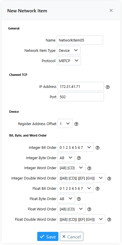
Network Item 05 Filled Out - Name — Enter any preferred name. For this example, we'll use
-
-
Repeat step 4 for network items 6 and 7. For network item 6, use IP address
172.31.41.72and port502. For network item 7, use IP address172.31.41.73and port502. Upon completing this step, the network tree should appear as shown below: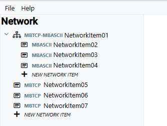
Network Items 6 and 7 -
Now we'll setup network item 8. This network item will be treated as a gateway that converts Modbus TCP to Modbus RTU, exactly the same as network item 1. Follow step 1 to create network item 8, but use IP address
172.31.41.74and port502. After creation of network item 8, the network tree should appear as shown below: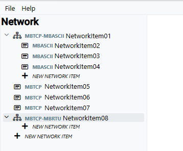
Network Item 8 -
To simulate network items 9, 10, and 11, repeat step 2 but add the network items underneath network item 8. For network item 9, use slave address
1. For network item 10, use slave address2. For network item 11, use slave address3. Upon completing this step, the network tree should appear as shown below: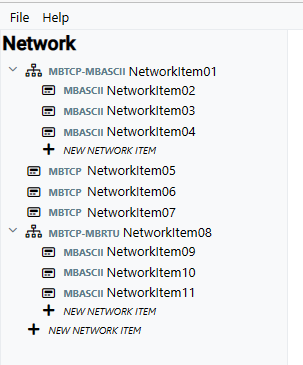
Network Items 9, 10, and 11